Outfitting the turntable!


.
.
.
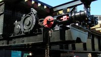
On Friday, engineers from Western Mechanical attached the south-end wheels and air motor to the turntable bridge. In the left hand pciture above, we see the motor on its frame cantilevered out from the frame carrying the wheel bearings. A wheel-bearing housing cap and retaining bar is visible between the bridge steel and the brake drum.
.
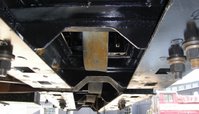
The picture in the centre above is an "ant's eye view" from below the rail head location looking upward. Three of the four wheel treads are visible as is the drive gear on the last wheel. A close look will reveal that all the support steel in this area is new, the old structure was so badly deteriorated as to be unusable.
.
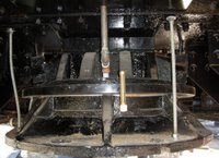
The last photo on the right shows the centre pivot assembly. The threaded rods are temporary supports to be removed. The brass fitting is an oil level gauge, behind which is a new steel overflow catch ring. The unpainted pipe is the oil feed line to the bearing from track level. Behind that, the horizontal bar is the side of a slide fitting that allows the entire bridge to be shifted slightly sideways. This is - we think - to allow both ends of the bridge to be properly aligned should the tracks not be perfectly lined up.
The last photo on the right shows the centre pivot assembly. The threaded rods are temporary supports to be removed. The brass fitting is an oil level gauge, behind which is a new steel overflow catch ring. The unpainted pipe is the oil feed line to the bearing from track level. Behind that, the horizontal bar is the side of a slide fitting that allows the entire bridge to be shifted slightly sideways. This is - we think - to allow both ends of the bridge to be properly aligned should the tracks not be perfectly lined up.
.
by Michael Guy, TRHA


<< Home